
The assembly instructions for a staircase may vary depending on its type and shape.
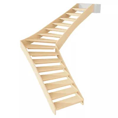
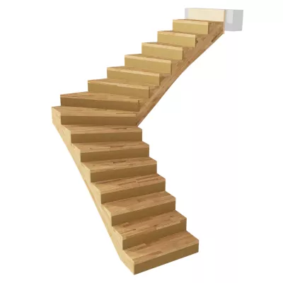
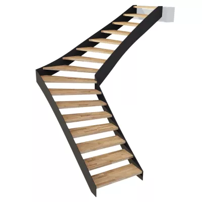
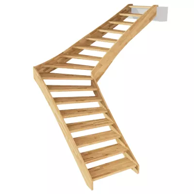
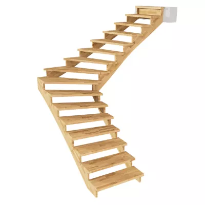
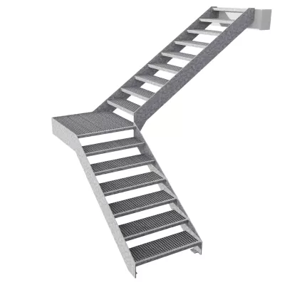
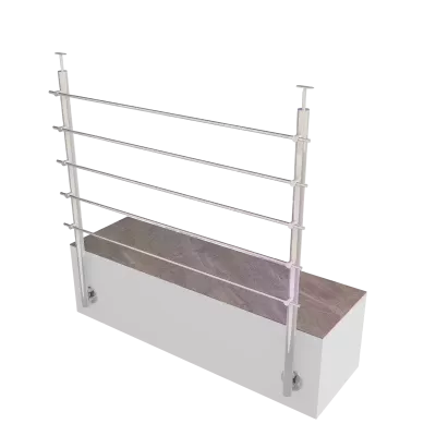
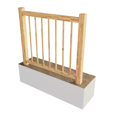
To make installing your staircase even easier and safer, we’ve prepared a clear step-by-step video alongside the detailed installation manual. It will guide you through the entire process and provide practical tips to ensure a smooth and hassle-free installation. Watch the video and assemble your staircase professionally, quickly, and with confidence.
We wish you a successful installation!
1. Preparation for Installation
Before beginning installation, carefully study the floor plan of the staircase and verify the ceiling opening and dimensions against the plan. Pay close attention to the wall structure, the ceiling structure, and the available space at the stair exit.
Check the completeness of all staircase components, unpack them, inspect them, and familiarize yourself with their position and layout in the stairwell. Follow the same process for the fittings and auxiliary materials required for installation.
Prepare all necessary assembly tools and aids. Read and understand the entire assembly sequence in advance to gain a theoretical understanding of all execution steps.
Personnel and Screwing Recommendations
2. Planning and Drilling Anchor Points
Assembly begins by anchoring the 2nd outer string (exit string) to the wall. Because the anchoring holes are not pre-drilled, they must be planned and drilled so that they do not collide with electrical installations, niches, or existing cavities in the wall.
If mounting against framed walls featuring reinforcements and studs behind plasterboard or OSB panels, align the anchor points exactly with the centres of these reinforcements. Do not economize on the number of anchor points; where necessary, place two anchors vertically one above the other to guarantee stability.
3. Aligning and Connecting the Outer Strings
Press the 2nd outer string (exit string) against the wall and guide it up to the exit edge. Support and align it carefully. The upper edge (saddle) of the vertical timber beam on the string must be positioned so that it sits lower than the final floor height of the upper floor by exactly the thickness of the tread.
Verify that the exit edge is perfectly level using a spirit level. It is particularly important to account for any unevenness at the stair exit, which is a frequent issue even with screed floors. If the final story height has not yet been established, bring the string to the correct height using suitable shimming plates. Once properly positioned, secure the string by anchoring it at all designated points, but do not tighten the anchors too firmly yet to maintain ease of alignment.
Next, glue the wooden dowels into the 1st outer string (ascent string). Screw the threaded rods into the 2nd outer string to join both strings at the outer corner. Coat the joint interface, especially the front face of the 1st outer string, evenly with glue.
Slide the outer ascent string onto the threaded rods and wooden dowels. Align the string with the corner, press it against the wall, support it, and adjust it carefully. Finally, screw the collar nuts onto the threaded rods in the side holes of the strings and tighten the corner connection securely.
3.1 Fine Alignment and Wall Anchoring
If the final story height is not yet fixed, use suitable shimming plates to bring the string to the correct elevation. Check the levelness of the saddle for the treads across both strings with a spirit level and make corrections if necessary.
Anchor the 1st outer string to the wall at all planned points, taking care not to tighten the anchors too firmly yet to allow for future fine adjustments.
Important Realignment Note: Ensure that the string does not become wavy by copying the unevenness of the wall. Use suitable shimming plates under the string to optimize its alignment and keep it flat.
Important Geometric Note: The delivered staircase is manufactured to be exactly rectangular in its floor plan. In case of deviations from a right angle at the exit, it is mandatory to shim the strings and the anchor plate accordingly so that they maintain the exact right angle after anchoring. Otherwise, the correct assembly of the steps, landing, and inner string will be severely compromised.
3.2 Exit String Threaded Rods
Screw the threaded rods into the two pre-drilled holes on the side of the vertical timber beam of the 2nd outer string (exit string). Ensure that the threaded rods engage firmly into the drive-in nuts located at the end of the holes.
Subsequently, insert a wooden dowel from above into the vertical timber beam, ensuring that it sits firmly and straight.
4. Pre-assembling the Exit Components
Prepare the 2nd inner string (exit string) by first gluing the wooden dowels into the two holes on its front face. Coat the front face of the string with glue, attach the exit post, and secure it firmly to the string using two 6×100 screws.
Next, screw the threaded rods into the two side holes of the exit post. Insert the exit tread into the housing/recess of the exit post, ensuring that the cutout fits precisely into the housing, and secure the step from the back of the post using a shorter screw.
Bring the exit inner string, together with the post and the exit tread, to the exit edge. Support the construction and align it carefully. The overlapping portion of the post on the inside must be placed onto the exit edge of the stair opening. The distance between the inner and outer string is defined by the anchor plate and the exit tread.
Now, place the exit tread onto the wooden dowel of the vertical timber beam of the outer string and secure this connection with glue. Apply silicone to the contact points of the string and the post where they interface with the anchor plate. Slide the anchor plate onto the threaded rods and press it firmly against the exit.
Finally, place the collar nuts onto the ends of all four threaded rods within the openings and tighten them firmly, ensuring all connections fit together cleanly and accurately.
5. Mounting and Anchoring the Exit Assembly
Plan the positioning of 2 to 4 holes in the anchor plate to secure it safely to the exit. Take into account the structural stability of the anchoring points and avoid potential conflicts with insulation or the routing of electrical, water, or heating lines. Drill the holes and anchor the plate firmly to the exit.
Status Check: At this stage, both outer strings are anchored to the wall, and the anchor plate and exit tread are securely fixed. On the inside, the 2nd inner string (exit string) is connected via the exit post to the anchor plate. This inner string currently remains only supported in the 1st inner corner and is free without a permanent anchor.
6. Connecting and Aligning the Inner Strings
Glue the wooden dowels into the 1st inner string (ascent string) to connect the strings at the 1st inner corner. Apply glue to the joint interface, specifically on the front face of the ascent string. Lift the string and connect it in the inner corner to the already mounted 2nd inner string. Secure this connection using two 6×100 screws.
Properly support and align the entire inner string assembly, similar to the outer sides. To better control the distance between the outer and inner strings, provisionally place a tread before the corner, another directly behind the corner, and tread No. 2 onto the wooden dowels. Verify the levelness during this test.
Once everything is correctly aligned, firmly anchor the ascent of the inner string to the floor under the first step using the floor anchor. The corresponding holes for this anchor are located under the 1st step.
Attention: Ensure that underfloor heating systems are strictly accounted for at this location!
Note: The floor anchor shares the hole on the side of the string with the future threaded bolt used to secure the first tread. Ensure that enough space remains for the threaded bolt!
7. Installation of Tread No. 1
8. Step-by-Step Installation of the Remaining Treads
Mount the remaining treads progressively from the ascent upwards:
Repeat this process step-by-step for every subsequent tread up to and including the second-to-last step.
8.1 Landing Installation
The landing is treated exactly like a standard tread during assembly, but due to its larger width, it must be secured with screws at multiple locations to ensure structural stability.
9. Tightening and Structural Inspection
Completely tighten all anchor points across the strings and the anchor plate, ensuring that all connections are permanently and properly fixed.
Thoroughly check the geometry and precision of the entire stair structure to ensure that all connections are perfectly aligned and that the staircase is stable and correctly mounted.
10. Installation of the Balustrade Posts
Now proceed with mounting the balustrade posts:
11. Installation of the Bottom Rails
Place the bottom rail onto the axis of the posts at the prescribed height and align it. Once positioned, screw the bottom rail firmly at both ends by driving the screws through the posts into the bottom rail. This permanently and securely connects the bottom rail to the balustrade posts.
12. Assembly of the Balusters and Handrails
Apply silicone into all holes intended for the balustrade balusters, both within the bottom rails and within the handrails.
Insert the balustrade balusters into the pre-drilled holes in the bottom rail according to the layout plan. Once all balusters are set, place the handrail on top of the balusters and screw it tight through the posts to establish a stable and solid assembly.
13. Cleaning and Finishing Work
After assembly is complete, clean the staircase thoroughly to remove dust and installation residues.
Cover all openings and connection holes with the custom-sized cover caps. Place the caps onto the holes with the rubber band side facing inward and press them firmly by hand to ensure they sit securely and flush with the surface.
14. Curing Time
All glued and silicone-sealed connections require approximately 24 hours at normal room temperature to cure completely. Do not subject the staircase to any structural loads or foot traffic during this period.